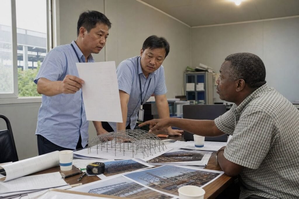
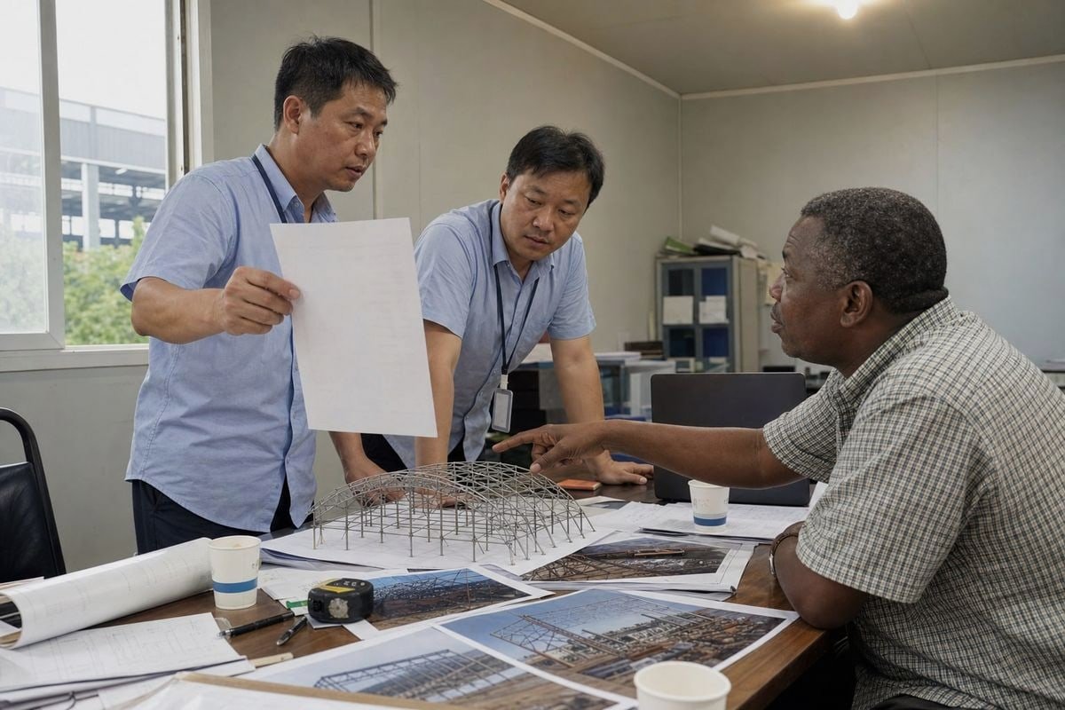
Sharing accurate on-site conditions is the foundation of good steel space frame 1 design. Our Xuzhou factory has seen incomplete site briefs delay projects by months, and I want to help you avoid that.
For steel space frame design, share your site survey data, soil bearing capacity, foundation status with as-built drawings, column layout, wind and snow loads, seismic zone classification, temperature range, corrosion exposure, and site access constraints. Complete site data prevents redesign, fabrication errors, and erection delays.
Each of these items answers a specific design question. Below, I break them into four groups so you know exactly what to prepare before you send an inquiry.
What Site Survey Data Should I Provide Before My Steel Space Frame Design Begins?
Last year, a contractor in Nigeria sent us only a span and a sketch. Our engineers had to pause the design twice waiting for surveyed support elevations. Good survey data would have saved three weeks.
Provide topographic survey data, a site plan with gridlines, surveyed support coordinates and elevations, existing structure dimensions, site utility locations, and any obstructions. If foundations already exist, include as-built drawings showing the actual column positions, not the original design drawings.
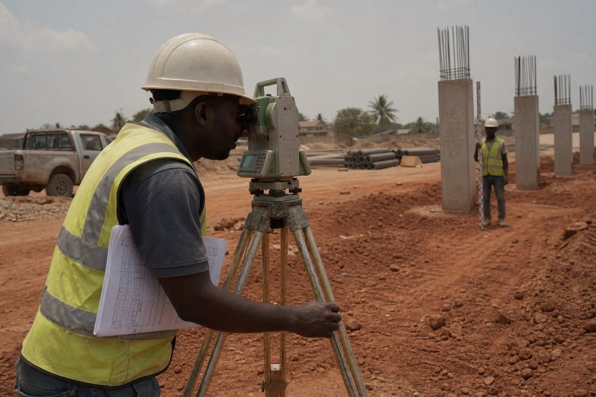
A space frame is a precise geometric system. Every steel tube and every bolt ball node is fabricated to fit exact coordinates. If your field dimensions differ from your drawings by even a few centimeters, the structural node connections 2 will not line up during erection. That is why we always ask for verified survey data, not just design intent.
The Difference Between Design Dimensions and Field Dimensions
Design drawings show what was planned. Field dimensions show what was actually built. Concrete work almost never matches the drawings perfectly. Columns shift. Elevations vary. For a space frame with hundreds of members, small deviations compound quickly. Some clients now send us 3D laser scan point clouds 3 of existing buildings. That data lets us reconcile theory with reality before we cut a single tube.
Minimum Survey Package We Recommend
| Survey Item | Why the Supplier Needs It |
|---|---|
| Site plan with gridlines | Sets the coordinate system for the whole design |
| Support point coordinates and elevations | Defines where every bearing node sits |
| Topographic survey data | Reveals slopes, drainage, and level differences |
| Site utility locations | Avoids clashes with buried pipes and cables |
| Existing structures and obstructions | Affects geometry, clearances, and lifting paths |
| As-built column layout (if built) | Confirms actual support geometry for fabrication |
One more point. Preliminary design can start with assumed dimensions. But final shop drawings must be based on verified field data. If you approve fabrication against assumptions, you carry the risk of misfit on site. We always confirm this handover point in writing before production begins.
How Do Soil and Foundation Conditions Affect My Space Frame Design Requirements?
Foundation status is the first thing our design team asks about on every new inquiry. It decides whether we adapt to your concrete or optimize the whole substructure for you.
Soil and foundation conditions determine support positions, bearing design, and settlement tolerance. If foundations are complete, provide civil as-built drawings and the actual column layout. If not, share soil bearing capacity data so the supplier can propose the foundation design and the optimal column arrangement.

From our project experience, this single question changes the entire workflow. So let me explain both paths clearly, because they lead to very different design outcomes.
Path One: Foundations Already Built
If your civil contractor has finished the foundations, we need the civil completion drawings and the actual constructed column layout. Not the original design set. The as-built set. Our space frame must land on your real columns, at their real positions and real elevations. We then design the bearing nodes, anchor bolts, and support geometry to match what exists on site.
Path Two: Foundations Not Yet Built
This is actually the better scenario for total project cost. If you send us your soil bearing capacity report before civil work starts, we can recommend the civil foundation design scheme and the optimal column layout for the space frame. A smarter column grid often reduces steel tonnage, simplifies structural node connections, and lowers foundation loads at the same time. On several stockyard projects, adjusting column spacing at this stage cut overall cost noticeably compared to fitting a frame onto a fixed grid.
Settlement Is a Design Load, Not an Afterthought
Differential settlement 4 matters more for space frames than for many other structures. Research references show that differential settlement can increase member forces near affected supports by 15% to 30%. So share your geotechnical report, any known soft soil zones, and required foundation settlement limits early.
| Foundation Status | What You Should Provide | What the Supplier Delivers |
|---|---|---|
| Foundations complete | Civil as-built drawings, actual column layout, anchor bolt positions | Frame designed to match existing supports exactly |
| Foundations not started | Soil bearing capacity report, geotechnical data | Proposed foundation scheme plus optimal column layout |
| Foundations in progress | Design drawings plus construction survey updates | Coordinated design with a final field verification step |
What Local Climate and Environmental Factors Should I Disclose to My Steel Structure Supplier?
Designing for a coal shed in coastal Indonesia is nothing like designing the same shed in Kazakhstan. Our engineers weigh corrosion, wind, snow, and temperature differently for every export market we serve.
Disclose your site-specific wind load requirements, snow and ice loads, seismic zone classification, extreme temperature range, and atmospheric corrosivity such as coastal salt, industrial dust, or chemical exposure. These inputs govern member sizing, bearing type, and corrosion protection requirements.
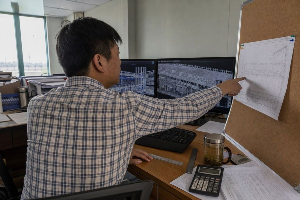
Some buyers push back here. They tell me the supplier should just design to the local code and be done with it. But codes give methods, not site values. Only you can tell us the actual wind speed at your site, the governing code edition, and the micro-climate around the building. One specification example we studied listed live load, dead load, wind load, and a temperature range from -20°F to 120°F as explicit design criteria. That level of detail is what a serious design brief looks like.
Thermal Movement Can Govern the Design
Space frames are long and continuous, so thermal expansion coefficients matter. For a 60-meter frame experiencing a 40°C temperature swing, thermal movement is substantial. In that case, supports typically need sliding bearings everywhere except one fixed point. If you do not tell us your temperature extremes, we cannot choose the right bearing strategy, and locked-in thermal forces can overload connections.
Environmental Exposure Checklist
- Basic wind speed and terrain category for wind load requirements
- Ground snow load and drift potential for snow and ice loads
- Seismic zone classification and local seismic code
- Maximum and minimum service temperatures
- Coastal distance, salinity, humidity, and rainfall patterns
- Industrial pollution, dust, or chemical vapors nearby
- Any ambient vibration sources, such as heavy machinery or rail lines, that could excite the lightweight lattice
On one dusty stockyard project, the exposure data drove special joint detailing and a heavier coating system. Corrosion protection requirements set at design stage cost far less than repainting a finished roof. Tell us the environment honestly, and the structure will last decades longer.
Why Does Sharing Accurate Site Access Information Help My Space Frame Project Avoid Delays?
A client in the Philippines once assumed our erection team could stage a large crane beside the building. The ground there was reclaimed fill. We redesigned the erection sequence to small-section high-altitude assembly instead, and the schedule survived.
Accurate site access information lets the supplier choose a feasible erection method, plan crane positions and lifting capacity, schedule deliveries, and design temporary works. Missing access data forces last-minute method changes, which cause schedule delays, extra cost, and safety risks.
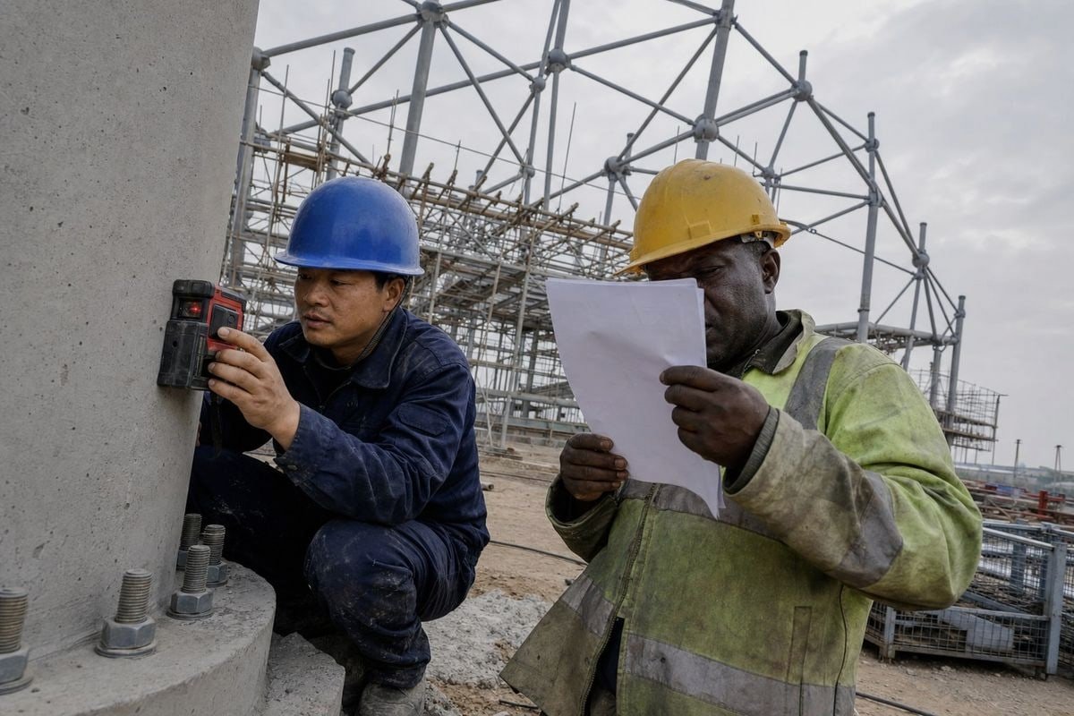
Erection is where space frame projects most often lose time. As an EPC contractor handling design, manufacturing, shipping, and installation, we plan the erection method during design, not after fabrication. The method affects temporary loads on the structure, member sizes during lifting, and even node design. So access information is design information.
What Access Data We Need Before Design
- Access road width, turning radii, and any bridge or gate limits for containers and oversized modules.
- Crane access and clearance, including ground bearing capacity for crane outriggers and overhead power lines.
- Available ground area for assembly, material storage, and tool rooms.
- Obstructions such as adjacent buildings, operating production lines, or roof equipment.
- Working-hour limits, security procedures, and permit requirements.
- Your preferred method, if any: ground assembly with a whole-unit lift, block lifting, or high-altitude bulk assembly.
How Access Constraints Change the Erection Method
| Site Condition | Likely Erection Approach | Schedule Impact |
|---|---|---|
| Open site, strong ground, big crane available | Ground assembly, then whole or block lifting | Fastest overall |
| Restricted ground, weak soil for cranes | High-altitude bulk assembly on platforms | Slower, but crane-light |
| Live plant with operating equipment below | Sequenced block erection with protection zones | Phased, needs careful erection sequence planning |
| Remote site, poor roads | Smaller shipping modules, more site bolting | Longer logistics lead time |
Case studies consistently highlight the same site-prep items: compacted and leveled working areas, temporary roads, storage space, and obstacle removal before erection starts. Specifications also require the erector to inspect supports and the work area before proceeding, and to stop if conditions are unsatisfactory. So site access is not background information. It is part of the design deliverable. When you share it early, our team can lock the erection sequence planning, confirm crane charts, and commit to a realistic installation schedule you can hold us to.
Conclusion
Complete on-site conditions protect your steel space frame project from redesign, misfit, and delay. Share survey data, foundation status, climate loads, and access constraints, and your supplier can deliver on time.
Footnotes
1. Wikipedia entry providing a technical overview of space frame systems and their geometric properties. ↩︎
2. The International Organization for Standardization provides global benchmarks for structural engineering and manufacturing quality. ↩︎
3. NIST develops standards for 3D metrology and laser scanning used to reconcile as-built conditions with designs. ↩︎
4. Technical explanation of how differential settlement affects structural integrity and load distribution in buildings. ↩︎




Leave a Comment
Have questions about steel space frame structures, or insights from your own projects? We'd love to hear from you -- your comment helps others in the industry.